Dry Gas Sealing Systems
Tandem Dry Gas Seals – Design & Maintenance Insights
Tandem Dry Gas Seals (DGS) have become the industry standard for centrifugal compressors due to their superior reliability and reduced maintenance compared to conventional lubricated seals. This paper outlines critical design and operational considerations to enhance seal performance and longevity. Key topics include:
- Seal Gas Supply & Conditioning: Emphasizes the importance of clean, dry gas to prevent contamination and ensure seal integrity.
- Primary & Secondary Seal Monitoring: Discusses venting strategies and health diagnostics for both seal stages.
- Separation Gas Control: Details the role of inert gases (typically nitrogen) in isolating the seal from bearing housing contaminants.
- Failure Modes & Mitigation: Identifies common degradation factors such as oil migration, hydrate formation, and poor filtration.
- Recommended Control Logic: Covers alarm, shutdown, and permissive conditions to safeguard seal operation.
The paper advocates for adopting best practices aligned with API 692 to improve compressor reliability and reduce lifecycle costs.
Introduction:
In the realm of high-performance turbomachinery, ensuring reliable containment of process gases is paramount.
Tandem dry gas seals, as standardized by API 692, represent a critical evolution in compressor sealing technology—offering non-contacting operation, modular support systems, and enhanced monitoring capabilities.
API 692 is an American Petroleum Institute (API) standard that provides guidelines for dry gas seal support systems used in compressors and expanders, particularly in the petroleum, chemical, and gas industries. It focuses on ensuring the reliability and safety of these systems by outlining requirements for design, application, testing, installation, and maintenance.
This article explores the design principles, functional streams, pressure dynamics, and troubleshooting strategies associated with tandem dry gas seals, providing engineers and operators with a comprehensive guide to optimizing seal performance and minimizing downtime.
What is a dry gas seal system?
API 692 introduces definition and terminology governing dry gas seal systems.
The process gas high pressure centrifugal compressors used in oil & gas industries requires highly safe and reliable operating requirement.
The dry gas seals are used to prevent the gas leakages from the compressors and plays roles as critical component. Hence the proper design and monitoring of dry gas seals are most important.
At their core, dry gas seal systems do two main jobs:
- providing a clean and conditioned environment for the dry gas seals.
- monitoring the health of the dry gas seal.
Types of dry gas seals are as follows: (Refer to Fig.1)
- Single
- Tandem with intermediate labyrinth seal
- Tandem without intermediate labyrinth seal
- Double

Fig.1. Types of dry gas seals
To accomplish these goals the dry gas seal system is usually broken down in five separate independent streams for tandem seals, and four streams for double seals.
These streams share some definitions and historically have been referred to by many different names.
Below are the API 692 names for the streams and a brief description, with reference to Fig.2.
1. Seal Gas (Sometimes referred to Buffer Gas):
- Seal gas flows across the primary seal (inboard stage) of the dry gas seal out towards the primary vent, and across the inboard process labyrinth, back into the process (compressor suction).
- Seal gas prevents dirty, unfiltered process gas from entering the dry gas seal. This gas must be cleaned and conditioned so as to be completely dry and free of particulate contamination.
- The conditioning is usually accomplished via the addition of filters and a gas conditioning unit, such as separators, boosters and heaters.
2. Secondary Seal Gas (Only applies to tandem seals):
(Sometimes referred to as Buffer Gas, Intermediate Injection or Intermediate Gas)
- This gas flows across the secondary seal (outboard stage) of a tandem dry gas seal and out the secondary vent, as well as across the intermediate labyrinth and out the primary vent.
- It is usually nitrogen and must also be cleaned and filtered to ensure the gas is dry and free from particulate matter. Not every seal will feature an intermediate labyrinth or secondary seal gas, but API 692 specifies them as standard.
- Secondary seal gas offers numerous benefits including vastly improving the ability to monitor the health of the secondary seal and improving the robustness of the secondary seal.

Fig.2. Tandem type dry gas seal
- This is realized by allowing back pressure to be generated quickly to achieve start permissive. The additional volume flow in the primary vent prevents spurious alarms and trips during transient operation conditions in the field, this is especially relevant for lower pressure applications where leakage rates for the inboard stage are low.
- Refer Fig.3. for flowchart of starting conditions for a gas compressor.

Fig.3. Conditional Flowchart: Secondary Seal Gas Impact
🛠 Operational Highlights:
- Back Pressure Threshold ensures that the secondary seal isn’t dry or vulnerable when the machine starts.
- Primary Vent Flow acts like a stabilizer: more flow, better differentiation between actual leakage vs normal transient blips.
- Interlocks are logic gates or conditions that ensure safety before proceeding with compressor activation.
- This flow is especially critical in low-pressure systems where signal strength from leakage is weaker and prone to misinterpretation.
3. Separation Seal Gas (Sometimes referred to as Buffer Gas or Tertiary Gas):
- This gas is injected between the two separation seal elements.
- If a labyrinth, it is injected between the two separation labyrinth halves,
if a carbon ring type seal (T93FR or the T83), then between a pair of carbon rings. - Separation seal gas prevents bearing oil ingress into the sealing area. Typically, separation seal gas is nitrogen or another inert gas, but air may also be used.
- If using air, particular care must be taken to avoid creating explosive mixtures in the secondary vent.
- These can be pressure or flow controlled dependent on customer preference. For clearance type seals, typically flow control is preferred due to the reduced nitrogen consumption rates.
- Flows are calculated to ensure a minimum velocity figure is achieved in all conditions to prevent oil ingress.
4. Primary Vent:
- The primary vent serves as a gas exit for leakage from the primary seal, and sometimes secondary seal gas.
- It is the main monitoring point for seal health, typically equipped with flowmeters and pressure transmitters.
- Leakage levels are key indicators, with alarms often set to thresholds like 10× guaranteed leakage.
- To stabilize readings, API 692 recommends backpressure control devices (regulator or orifice) within the vent:
- They generate controlled backpressure, improving secondary seal monitoring.
- This dampens pressure noise and enhances trend clarity.
- In vent studies, proper instrumentation and backpressure tuning are critical, as they influence the pressure cascade and dry gas seal system accuracy.
5. Secondary Vent:
- The secondary vent carries leakage from the outboard (secondary) seal and the inboard side of the separation seal.
- It must remain unrestricted—backpressure risks reverse pressurization of the secondary seal due to low differential pressures.
- Pressure should be maintained near atmospheric, with very low flowrates.
- API 692 allows optional pressure and flow monitoring, though John Crane advises against it, citing minimal utility.
- Element analyzers are optionally permitted for select applications but are not typical for most installations.
How Backpressure Devices in primary vent aid Secondary Seal Monitoring:
a. Creates a Defined Pressure Gradient
- By adding backpressure in the primary vent, the system raises the pressure in the intermediate chamber between the primary and secondary seals.
- This elevates the downstream pressure slightly above atmospheric, ensuring the secondary seal is not exposed to vacuum conditions or unstable pressure zones.
- A stable gradient allows accurate readings of secondary seal gas flow or leakage, improving detectability of anomalies.
b. Damps Transients and Sensor “Noise”
- Flowmeters and pressure transmitters in the primary vent can show erratic readings during startup or pressure dips.
- Backpressure acts as a hydraulic cushion, smoothing out rapid fluctuations.
- This reduces false alarms and helps trend lines reflect actual seal behavior instead of noise.
c. Improves Isolation Between Seal Stages
- Without controlled backpressure, leakage from the primary seal could evacuate too rapidly, masking small but crucial leak signals from the secondary seal.
- Controlled venting creates an environment where both primary and secondary leakage paths are distinguishable—instrumentation can “see” them more clearly.
d. Enables Repeatable Conditions for “Vent Studies”
- Studies examining vent flow characteristics, alarm calibration, and leakage trends rely on consistent pressure staging.
- A backpressure regulator or orifice lets you tune and lock down those conditions, providing reliable baselines across operating cycles.
6. Gas Conditioning unit:
- One of the leading causes of gas seal failure is improperly conditioned gas entering the seals.
- All gas must be both clean and dry, before it goes across seal faces. GCUs condition the gas protecting the seal.
- GCUs are typically made up of four items: filters (coalescing and separators), heaters, boosters and coolers. The most significant change is that now these items should be considered as standard.
- Meaning that sufficient justification must be made by the system vendor not to include such feature as heaters and boosters.
Function of Dry Gas Seals:
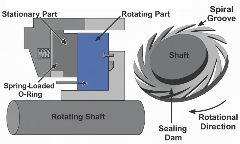
- The key elements within a Gas Seal are the sealing faces and secondary sealing elements (Fig.4).
- A shaft sleeve, which is fixed with the compressor shaft, holds the rotating seat.
- The rotating seat is sealed against the shaft sleeve with a secondary sealing element, which is a special O-ring or PTFE filled sealing device.
- The rotating seat has the gas grooves integrated to generate an aerodynamic lift off and provide gas film stiffness during operation.

Fig.4.Dry Gas seal components
- The non-rotating elements combine a seal housing, fixed to the compressor casing, and the non-rotating seal face.
- The stationary elements are designed to compensate for axial movements of the compressor rotor in relation to the compressor case.
- The compressor shaft is exposed to axial movement caused by different loads, case expansion from heat and pressure or vibrations.
- Compensation for axial movements is achieved by allowing the non-rotating face to move along the balance sleeve (sleeve below the non-rotating face, item 2).
- The nonrotating face is sealed against the balance sleeve with a dynamic sealing element (O-ring or PTFE filled sealing device), which slides on the balance sleeve.
- When pressure is applied to the seal or the compressor is rotating, the applied forces will hold the seal faces off and maintain the appropriate gap of 3 to 5 microns between them.
- When these conditions are not present springs are required to hold the seal faces together.
- To avoid any wear on the sealing faces, Gas Seals are designed to lift off when operated. This means the rotating seat and stationary face have no contact in operation.
- The seals are kept from touching by the generation of hydro-dynamic pressure, created by small grooves cut into the face of the rotating ring which draws gas into the seal, forcing the two surfaces apart.
- Because the space between the seals is less than human hair, the sealing gas used must be completely dry and free from grit, dust, or moisture. An external source of sealing gas is therefore used to ensure cleanliness.
- This separation is called lift off. The lift off is mainly influence by two effects (Fig.5):
- Differential pressure over the faces
- Circumferential speed

Fig.5. Seal lifts off while running
- The seal can lift off at a certain differential pressure, a certain speed or a combination of speed and differential pressure.
- The lift off speed and differential pressure depends on the specific operating conditions, like gas type, and detailed seal design.
- The tandem seal system is designed so that after the failure of the primary seal, the machine can be safely shut down using the containment provided by the secondary seal without a hazardous release of gas into the atmosphere.
- Although these dry gas seals are able to handle high levels of vibration without damage, reverse rotation of the shaft at high speeds will damage the seals as they are not able to develop the hydro-dynamic pressure required to push the sealing faces apart. Fig.6 shows the sealing face spiral groove arrangement.
- The most common gas seal arrangements used in the industry for compressors are:
-tandem arrangements (Fig.7) or
-tandem with intermediate labyrinth arrangements (Fig.8).

Fig.6. Dry gas seal components

Fig.7. Tandem Seal Schematic
Dry Gas Seal control system:
- Dry Gas Seal and barrier gas control systems are specially designed to supply gas, at the correct pressure and flow, to the dry gas seals.
- These systems are panel-mounted and installed adjacent to the compressor skid.
- The DGS will have reliable operation only if the gas is clean. The seal gas filter is installed to filter the contaminants.
- Ingress of foreign material into the running gap of the seals leads to degrade sealing performance (increased gas leakage) and eventual failure of the seal.

Fig.8. Tandem Seal with Intermediate Labyrinth Schematic
Control system provides three main functions:
- Filtration of Seal gas & Buffer Gas
- Regulation of Seal gas & Buffer Gas
- Monitoring of seal Performance
- Design is simple to operate and user friendly with minimum maintenance requirements.
Seal Gas loop:
- Seal gas must be dry and free of particles less than 3 micron.
- Sealing gas is injected between the inner labyrinth seal and the Dry gas seal.
- The majority of this gas flows across the inner labyrinth seal and into the compressor or process side of the Compressor.
- A very small amount of the sealing gas passes through the primary seal & out of the primary vent which is normally connected to user’s flare system. Refer Fig.9,10,11.

Fig.9. Dry gas seal control system layout

Fig.10. Dry gas seal (tandem type) arrangement

Fig.11. Dry gas Tandem type seal

Fig.12. Dry gas seal location on compressor shafting
Pressure Balancing:
- The thrust created by the high-pressure discharge pushing the compressor rotor back towards the suction is canceled by creating opposing thrust using a balance drum. (Fig.12)
- This pressure balancing system also means the compressor seals are only ever exposed to suction pressure.
🛠️ Overview of Tandem Dry Gas Seals (API 692):
Tandem dry gas seals are non-contacting mechanical seals used in centrifugal compressors to prevent process gas leakage.
API 692 standardizes their design, support systems, and monitoring requirements for enhanced reliability and safety in oil, gas, and petrochemical industries.
🔍 Key Features:
- Dual sealing stages: Primary and secondary seals arranged in series.
- Intermediate labyrinth: Optional, adds a buffer zone between seals.
- Non-contacting faces: Grooved rotating ring and flat stationary ring maintain a micron-level gap.
- Gas-lubricated: Uses clean, dry gas to create a pressure barrier and lubricate seal faces.
- Modular support systems: API 692 mandates separate modules for filtration, conditioning, and monitoring.
🧩 Key Design Advantages:
- Dry running: No liquid contamination, enhancing longevity.
- Modular support systems: Easy maintenance and standardized interfaces.
- Non-contact operation: Minimizes wear and friction.
- Continuous monitoring: Vent flows, pressure diff, and temperature.

Table 1. Functions of dry gas sealing elements

Table 2. Typical Operating profiles
These values vary based on compressor design, operating conditions, and seal configuration. Always consult OEM specs for exact figures.
⚠️Common Faults & Defects:
- Contamination: Entry of liquid hydrocarbons, particulates, or lube oil into seal faces.
- Improper gas conditioning: Leads to condensation and seal face damage.
- Seal face wear: Due to dry running or misalignment.
- Pressure imbalance: Can reverse pressurize seals, causing failure.
- Instrumentation failure: Faulty flowmeters or transmitters can mask early warning signs.
- High Vent flows: Excess leakage, worn seal faces.
- Bearing Oil Ingress: Inadequate separation seal pressure.
🔧Troubleshooting Tips:
- Monitor differential pressure across seal faces for early warnings of leakage paths.
- Check vent flow rates for abnormal leakage, regularly.
- Inspect filter elements regularly for clogging or liquid accumulation.
- Ensure proper seal gas superheat to avoid condensation (typically 20°F above dew point).
- Verify separation gas supply to prevent oil migration.
- Verify instrumentation and alarm thresholds for correct operation.
✅ Conclusions:
- Tandem dry gas seals are more than just mechanical barriers—they are dynamic systems that rely on precise gas staging, clean operation, and vigilant monitoring.
- By adhering to API 692 guidelines and understanding the interplay of seal pressures, support streams, and failure modes, operators can significantly improve compressor reliability and safety.
- Whether in design, commissioning, or maintenance, a deep grasp of these seals empowers teams to prevent costly failures and extend equipment life in demanding industrial environments.
📚 References & Further Reading on Tandem Dry Gas Seals:
- Dry Gas Sealing Systems for Axial, Centrifugal, Rotary Screw Compressors & Expanders, API STANDARD 692, FIRST EDITION, JUNE 2018.
- API 692 Seal Gas systems, Design guidelines- John Crane
- Asia Turbomachinery & pump symposium-Singapore, 22-25 Feb 2016, DRY GAS SEAL CONTAMINATION DURING OPERATION AND PRESSURIZED HOLD – BACKGROUND AND POTENTIAL SOLUTIONS.
- Asia Turbomachinery & pump symposium-Singapore, 22-25 Feb 2016, Dry gas seal failure and troubleshooting Manikandan, A GE Oil & Gas, Doha, Qatar, Moorthy Subramanian Eagle Burgmann Middle East FZE, UAE.


Venkat Krishna Soundarraja
Mr. S. Venkat Krishna is the Chief Data Officer at Volteo Maritime, with a background as a Marine Engineer. He brings over 28 years of sailing experience, including 15 years as a Chief Engineer in the tanker industry. A Fellow of the Institution of Marine Engineers (India), he specializes in condition monitoring, data analytics, and reliability engineering. His expertise spans crude oil, product, and chemical tankers, as well as bulk carriers and container vessels.
In his current role, he focuses on ensuring data quality, driving the adoption of AI and machine learning, and enabling data-driven decision-making to enhance organizational performance. Proficient in Python, R, and Power BI, he plays a key role in transforming data into a strategic asset.
Mr. Krishna is also a visiting faculty member, technical mentor, and published researcher, with a strong passion for innovation, education, and emerging technologies. Outside of work, he enjoys singing and artistic sketching—blending creativity with technical precision.
Leave a comment
View more
Give your career a boost with S&B professional services.
CV Prep/EvaluationMore Jobs
Ship management
Mumbai
Senior Executive – Brandin..
Ship management
Mumbai
Assistant Manager – Vessel..
Ship management
Mumbai
HR Officer
Interview Prep/Mentoring
Find your polestar with the host of experts available on our platform
Know more

Contact Us